Serial UART connection RPI zero / Arduino

You can connect the RPI and Arduino is several ways, eg. Serial/UART, I2C or USB. With I2C you can connect several device on the same wire. 1:1 communication is now suffiecient so I will go for the Serial/UART connection.

The RPI operates at 3.3V and the arduino I have chosen on 5V. Therefor we should use a Logic Level Converter (LLC) for serial/UART communication. If you are going for I2C please use the I2C converter.

Wiring

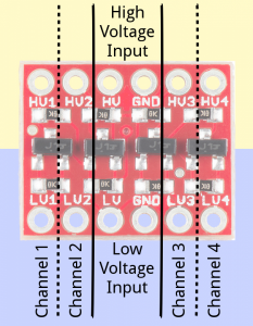
There are 12 total pins on the LLC – two parallel rows of six headers. One row contains all of the high voltage (e.g. 5V) inputs and outputs, the other row has all things low voltage (e.g. 3.3V).

The voltage supplied to the HV and GND inputs should be higher than that supplied to the LV side. For example, if you’re interfacing from 5V to 3.3V, the voltage on the HV pin should be 5V, and the voltage on LV sould be 3.3V.

There are four separate data channels on the BD-LLC, each capable of shifting data to and from high and low voltages. These pins are labeled HV1, LV1, HV2, LV2, HV3, LV3, HV4, and LV4. The number at the end of each label designates the channel of the pin, and the HV or LV prefix determines whether it’s on the high or low side of the channel.

A low-voltage signal sent in to LV1, for example, will be shifted up to the higher voltage and sent out HV1. Something sent in HV3 will be shifted down and sent out of LV3. Use as many of these channels as your project requires.
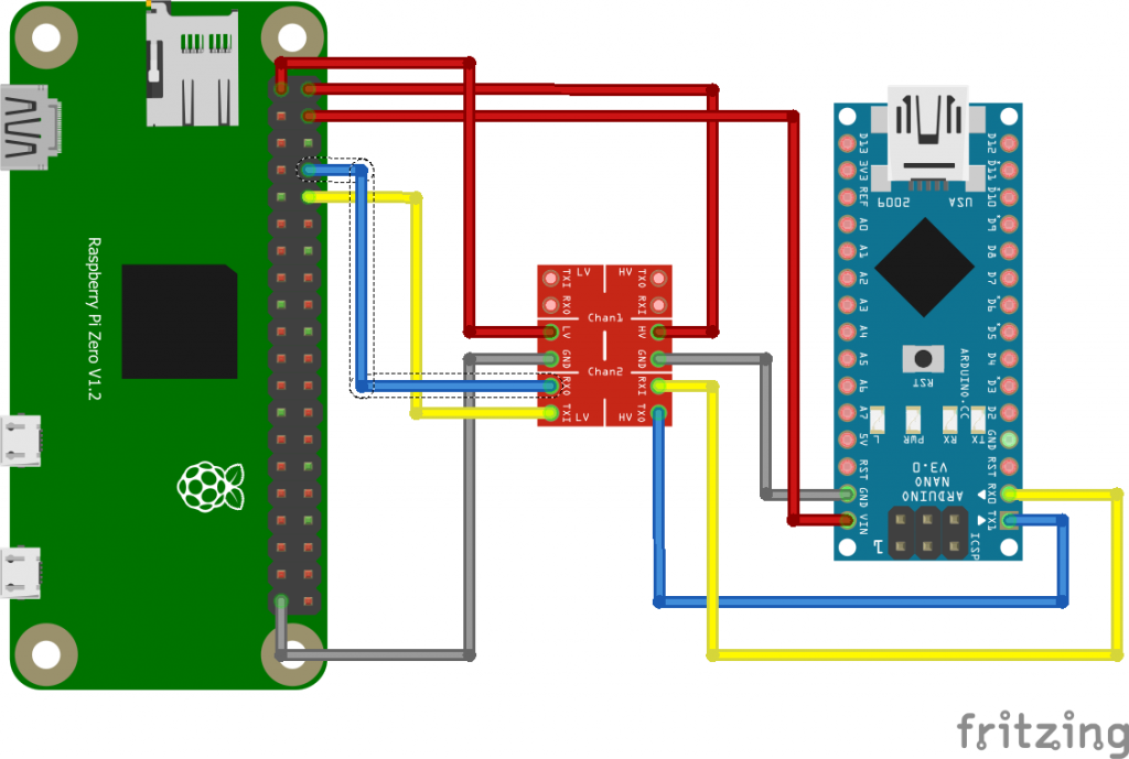
The RPI is the low level side and the Arduino on the high level side. Please note that for the GPIO the RPI uses 3.3V, but still it has pins to provide 5V. I use the RPI 5V pins to provide power to the Arduino Nano board. We can also use the other RPI 5V pin to provide the HV side for the Arduino. We also need to twist the TX/RX, check this cross on the LLC board (blue/yellow crossing).

RPI config
The RPI is not yet configured to use the serial for communication. Please perform the following steps:
You can use “raspi-config” utility to enable the UART:
1. sudo raspi-config
2. Under “Interfacing Options”, choose “Serial”.
3. Say “No” when it asks if you want a login shell over serial.
4. Say “Yes” when asked if you want the hardware enabled.
5. Finish, then accept the offer to reboot.

After this configuration change and the wiring you are ready to check if the serial communication is ready to use. First you can check if ttyS0 is available on the RPI side with the command ls -l /dev/ttyS0, you should see the following output: crw-rw—- 1 root dialout 4, 64 Mar 22 19:16 /dev/ttyS0

The fastest way to check the communication is to load the following program into your arduino:

int x = 0; // variable

void setup() {
Serial.begin(9600); // open the serial port at 9600 bps:
}

void loop() {
// print labels
Serial.print("NO FORMAT"); // prints a label
Serial.print("\t"); // prints a tab

Serial.print("DEC");
Serial.print("\t");

Serial.print("HEX");
Serial.print("\t");

Serial.print("OCT");
Serial.print("\t");

Serial.print("BIN");
Serial.print("\t");

for(x=0; x< 64; x++){ // only part of the ASCII chart, change to suit

// print it out in many formats:
Serial.print(x); // print as an ASCII-encoded decimal - same as "DEC"
Serial.print("\t"); // prints a tab

Serial.print(x, DEC); // print as an ASCII-encoded decimal
Serial.print("\t"); // prints a tab

Serial.print(x, HEX); // print as an ASCII-encoded hexadecimal
Serial.print("\t"); // prints a tab

Serial.print(x, OCT); // print as an ASCII-encoded octal
Serial.print("\t"); // prints a tab

Serial.println(x, BIN); // print as an ASCII-encoded binary
// then adds the carriage return with "println"
delay(200); // delay 200 milliseconds
}
Serial.println(""); // prints another carriage return
}

This arduino program will print out a list of dec, hex and binair numbers on the serial interface of the arduino.

Now enable the RPI side with:
sudo apt-get install minicom
sudo minicom -b 9600 -o -D /dev/ttyS0

To exit minicom: Hit enter, then ctrl-a then q then press “enter”
RPI installation without monitor, keyboard(Headless) and finalizing the config

I just bought a RPI zero and lacking a micro HDMI. Any way when installing a RPI2 or 3 I still do not want to connect a keyboard and monitor. Please perform below steps to make an installation without monitor and keyboard (headless). We will enable SSH login (disabled with newer raspbian images), configure the Wifi and finalize the installation. In the last steps I will expand the file system and add additional security measures, e.g. removing the PI user and setting up a firewall. So please download and write the raspbian image to your SD card.

Enabling Wifi and SSH access is done by writing a file to /boot/ of the SD card.

Enable Wifi: If a wpa_supplicant.conf file is placed into the /boot/ directory, this will be moved to the /etc/wpa_supplicant/ directory the next time the system is booted, overwriting the network settings.
ctrl_interface=DIR=/var/run/wpa_supplicant GROUP=netdev
update_config=1
country=your_ISO-3166-1_two-letter_country_code

network={
ssid="your_SSID"
psk="your_password"
key_mgmt=WPA-PSK
}

Location and filename: /boot/wpa_supplicant.conf

Replace your SSID, password and ISO-3166 in the config file. Your_ISO-3166-1_two-letter_country_code is your ISO Country Code (such as NL for Netherlands).

[Problem] Wifi not working with RPI3 B+: With the RPI zero above process worked, with the RPI3 B+ I run into problems with the wifi. I executed: sudo raspi-config, under localisation options selected change wifi country and then sudo rfkill unblock wifi. Now my wifi worked. [/Problem]

Enable SSH Raspbian will look for a file named ssh on the boot partition at startup and will enable sshd, which by default is disabled. So please create an empty file “ssh”

Location and filename: /boot/ssh

Expand file system We do this to make use of all the space present on the SD card as a full partition. All this does is, expand the OS to fit the whole space on the SD card which can then be used as the storage memory for the RPI.

sudo raspi-config
Option 7:Advanced options
A1: Expand file system

Update firmware It’s always good practice to run the latest version of the firmware which also included the latest bug fixes.

sudo rpi-update

Add user I do not want to continue to use the PI user for security reasons, that’s why we should create a new user with sudo rights.

sudo adduser --gecos "" replace_with_username
sudo usermod -aG sudo replace_with_username

–gecos: Set the gecos field for the new entry generated. Adduser will not ask for finger information if this option is given.

-aG add in group
Now it would be nice if only this user could login via SSH and that we disable root login:
sudo nano /etc/ssh/sshd_config
Add, edit, or append to the end of the file the following line, which contains the usernames you wish to allow to log in
AllowUsers add_with_username
PermitRootLogin no
After the change you will need to restart the sshd service using sudo systemctl restart ssh or reboot so the changes take effect.

Disable Pi user login Everybody knows that on a RPI the user PI is available, so for security reasons I would like to delete this PI user. Please login with your new created user.

sudo deluser pi
sudo passwd root

Change hostname You can change the hostname of the RPI (default: raspberry) by editing the hostname file:  sudo nano /etc/hostname

Firewall We still want to block access to the RPI on any ports that are not explicitly enabled.

apt-get install -y ufw
sudo ufw allow ssh
sudo ufw --force enable
sudo ufw status

Now your RPI is ready to rock!

Arduino yun MQTT Tutorial

In this tutorial we will dive into the use of MQTT with the arduino yun (or linkit) to control the LED#13.

One of the common protocols used in the IOT world is MQTT. MQTT is a machine-to-machine (M2M)/”Internet of Things” connectivity protocol. It was designed as an extremely lightweight publish/subscribe messaging transport. It is useful for connections with remote locations where a small code footprint is required and/or network bandwidth is available.

MQTT
The MQTT protocol is based on the principle of publishing messages and subscribing to topics, or “pub/sub”. Multiple clients connect to a broker and subscribe to topics that they are interested in. Clients also connect to the broker and publish messages to topics. Many clients may subscribe to the same topics and do with the information as they please. The broker and MQTT act as a simple, common interface for everything to connect to.

The setup
1.) MQTT broker running on a RPI
2.) Python script on the arduino yun (openwrt)
3.) Sketch for the MCU

MQTT broker
To install the MQTT broker:

apt-get update
apt-get install mosquitto

To test it open two SSH connections. One for subscribing and the other for publishing.

mosquitto_sub -h 192.168.2.40 -t "arduino/led"
mosquitto_pub -h 192.168.2.40 -t "arduino/led" -m "1"
mosquitto_pub -h 192.168.2.40 -t "arduino/led" -m "0"

Result:

1
0

For debugging purposes you can also run mosquitto in a shell. So open up the third SSH connection. Execute “/etc/init.d/mosquitto stop” and then execute “mosquitto”. Output:

1468435883: mosquitto version 1.3.4 (build date 2014-08-22 06:10:51+0000) starting
1468435883: Using default config.
1468435883: Opening ipv4 listen socket on port 1883.
1468435883: Opening ipv6 listen socket on port 1883.
1468435883: New connection from 192.168.x.x on port 1883.

Python
Install the MQTT python client:
pip install paho-mqtt

And then use the following python code:


#!/usr/bin/python
import sys
import paho.mqtt.client as mqtt

sys.path.insert(0, '/usr/lib/python2.7/bridge/')

from bridgeclient import BridgeClient as bridgeclient

from tcp import TCPJSONClient
json = TCPJSONClient('127.0.0.1', 5700)

value = bridgeclient()


# The callback for when the client receives a CONNACK response from the server.
def on_connect(client, userdata, rc):
    print("Connected with result code "+str(rc))
        # Subscribing in on_connect() means that if we lose the connection and
        # reconnect then subscriptions will be renewed.
    client.subscribe("arduino/led")

# The callback for when a PUBLISH message is received from the server.
def on_message(client, userdata, msg):
        print(msg.topic+" "+str(msg.payload))
        json.send({'command':'put', 'key':'led', 'value':msg.payload})

client = mqtt.Client()
client.on_connect = on_connect
client.on_message = on_message

client.connect("192.168.x.x", 1883, 60)

# Blocking call that processes network traffic, dispatches callbacks and
# handles reconnecting.
# Other loop*() functions are available that give a threaded interface and a
# manual interface.
client.loop_forever()

Normally I would use value.put() instead of using json.send() only I received a “Bad file descriptor” once in a while. As the arduino yun uses JSON via TCP to the bridge library I used this workaround instead.

Sketch
Upload the sketch. memset will set al the items in the array to zero.

#include <Bridge.h>
#include <stdio.h>
 
// Here we will hold the values coming from Python via Bridge.
char ledvalue[2];
 
void setup() {
  // Zero out the memory we're using for the Bridge.
  memset(ledvalue, 0, 2);
   
  // Initialize digital pins 13 as output.
  pinMode(13, OUTPUT); 
 
  // Start using the Bridge.
  Bridge.begin();
}
 
void loop() {
  
  
  // Write current value of D13 to the pin (basically turning it on or off).
  Bridge.get("led", ledvalue, 2);
  int ledD13 = atoi(ledvalue);
  digitalWrite(13, ledD13);
   
  delay(10);  
}

Please note that the delay for retreiving info from the bridge is rather low, causing heavy load on the linux side.

Update [29-12-2017]:
If you receive the following error: TypeError: on_connect() takes exactly 3 arguments (4 given) the following could help you. Paho-mqtt client has been updated and you need to change the following (1. on_connect and subscribe):

def on_connect(client, userdata, rc):
print(“Connected with result code “+str(rc))
# Subscribing in on_connect() means that if we lose the connection and
# reconnect then subscriptions will be renewed.
client.subscribe(“arduino/led”)

Should be changed to:
def on_connect(self, client, userdata, rc):
print(“Connected with result code “+str(rc))
# Subscribing in on_connect() means that if we lose the connection and
# reconnect then subscriptions will be renewed.
self.subscribe(“arduino/led”)

Start nodejs script during bootup on your RPi

If you have written a nodejs script you want to be able to run this application as a daemon on your linux system. For this purpose you could use Forever. The purpose of Forever is to keep a child process (such as your node.js web server) running continuously and automatically restart it when it exits unexpectedly. In this article you can find how to install forever and launch a nodejs script in init.d.

Installation

sudo npm -g install forever

Command Line Usage
You can use forever to run scripts continuously (whether it is written in node.js or not).
Start:

forever start server.js
Output:
warn:    --minUptime not set. Defaulting to: 1000ms
warn:    --spinSleepTime not set. Your script will exit if it does not stay up for at least 1000ms
info:    Forever processing file: server.js

Stop:

forever stop server.js
Output:
info:    Forever stopped process:
    uid  command             script    forever pid   id logfile                 uptime
[0] MKqv /usr/local/bin/node server.js 19915   19920    /root/.forever/MKqv.log 0:0:1:14.969

Start script during boot
To start your script during boot on your raspbian you will need to create a script in /etc/init.d. In this example I will use a script called nodestart to which you can provide two arguments “start” and “stop”. The nodejs script is called “server.js”.

#!/bin/sh
#/etc/init.d/nodestart

export PATH=$PATH:/usr/local/bin
export NODE_PATH=$NODE_PATH:/usr/local/lib/node_modules

case "$1" in
  start)
  exec forever --sourceDir=/[directory to your script] -p /[log directory] server.js
  ;;
stop)
  exec forever stopall
  ;;
*)
  echo "Usage: /etc/init.d/nodeup {start|stop}"
  exit 1
  ;;
esac

exit 0

Your almost there! Make the script executable and install it:

chmod 755 /etc/init.d/nodestart
update-rc.d nodeup defaults

Now it will be automatically started during boot or you can try it via the CLI:

/etc/init.d/nodestart start

You can remove the script via:

update-rc.d -f nodestart remove

Install nodejs on RPi2

Unfortunately nodejs is no longer maintained via an installation of apt-get install on the raspberry PI. Please use below instructions for the installation.

Be sure that you first remove the old one:

sudo apt-get remove nodejs

Then check on the nodejs site the latest version: https://nodejs.org/dist/latest/
In my case it is: node-v6.0.0-linux-armv7l.tar.gz

For the RPi1 use should use armv6l.tar.gz

Now it’s time to download and install.

wget https://nodejs.org/dist/latest/node-v6.0.0-linux-armv7l.tar.gz
tar -xvf node-v6.0.0-linux-armv7l.tar.gz 
cd node-v6.0.0-linux-armv7l
sudo cp -R * /usr/local/

Your done! Now check that it is working by node -v

RC522 with Raspberry Pi 2

The RC522 is a cheap RFID module that can read and write Mifare’s tags and being sold at several web stores, like eBay and included with many “starter kits” nowadays. Simply search RFID-RC522 (MF-RC522). The card reader and the tags communicate using a 13.56MHz electromagnetic field. (ISO 14443A standart tags)

Wiring up:

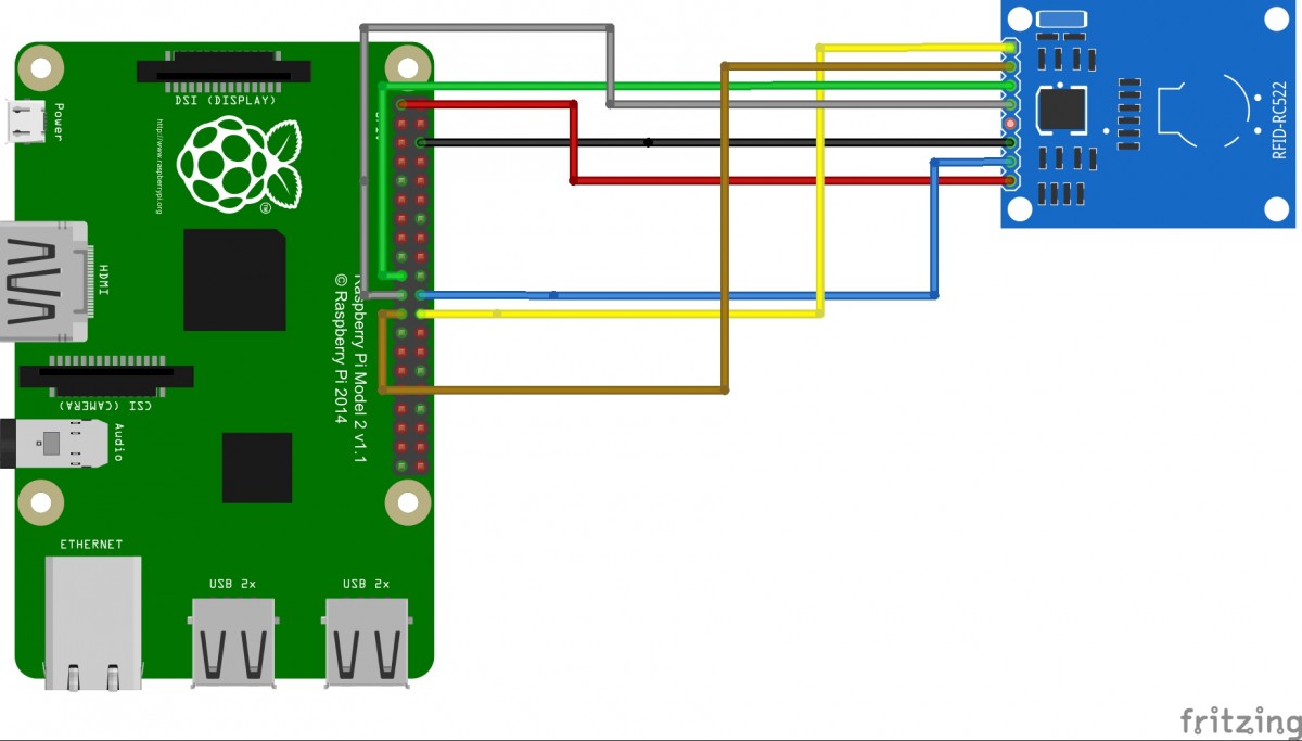
Below table shows the connection between RC522 and RPi2:

RC522 pin RPi2 pin nr RPi2 pin name
SDA 24 GPIO8
SCK 23 GPIO11
MOSI 19 GPIO10
MISO 21 GPIO9
IRQ Remark: Not connected
GND GND GND
RST 22 GPIO25
3.3V 1 3V3

Please note that the RPi2 has a 40 pin header (RPi1 has 25).

Wiring RPi2 and RC522

RPi2 steps:

We need to enable all the python libraries and the SPI interface on the RPi2 to get it working.

To install the python environment:

sudo apt-get install python-dev

enable spi interface:
Edit the file /boot/config.txt and add the following two lines:

device_tree_param=spi=on
dtoverlay=spi-bcm2708

To check if the SPI interface is working, please reboot the RPi and run the following instructions:

$ dmesg | grep spi

The output will look like:

[ 10.886588] bcm2708_spi 3f204000.spi: master is unqueued, this is deprecated
[ 10.901487] bcm2708_spi 3f204000.spi: SPI Controller at 0x3f204000 (irq 80)

Now download and install the SPI python library:

git clone https://github.com/lthiery/SPI-Py.git
$ cd SPI-Py
$ sudo python setup.py install

Now download and run the RC522 lib:

$ git clone https://github.com/rasplay/MFRC522-python.git
$ cd MFRC522-python
$ python read.py

The output will look like:

Card detected
Card read UID: 98,40,242,197,125

Turn your Raspberry PI into a malicious network traffic scanner with wireshark

I needed to scan a network with wireshark to check for malicious traffic. I took my RPi turned into a router with a DHCP server and installed wireshark to check all the network traffic.

Step 1: Static IP address

See my previous article for the setup.

Step 2: Install and configure DHCP server

In this case I’ve chosen the ISC as DHCP server. To install:

sudo apt-get install isc-dhcp-server

For the configuration, please edit /etc/dhcp/dhcpd.conf and add the following:

subnet 192.168.100.0 netmask 255.255.255.0 {
range 192.168.100.20 192.168.100.39;
option broadcast-address 192.168.100.255;
option routers 192.168.100.1; option domain-name-servers 8.8.8.8;
}

Now we need to tell the daemon some specifics, please edit /etc/default/isc-dhcp-server and uncomment the following:

DHCPD_CONF=/etc/dhcp/dhcpd.conf
DHCPD_PID=/var/run/dhcpd.pid
INTERFACES="eth0"

And add “eth0” to the interfaces list, this tells the daemon on which interface he needs to react on.

Before you run the DHCP server please stop the DHCP server on your rputer. Now you can start the daemon on your RPi with: sudo service isc-dhcp-server start

If you run into any problems please use systemctl status isc-dhcp-server.service to check the output.

You can use cat /var/lib/dhcp/dhcpd.leases to check out the leases.

Step 3: Turn your RPi into a router

Your RPi is now able to respond to DHCP requests, but now we need to be able to forward the traffic.

sudo bash -c 'echo 1 > /proc/sys/net/ipv4/ip_forward'

Please edit /etc/sysctl.conf and uncomment out the line that says net.ipv4.ip_forward = 1
Last step is to enable NATTING via IPtables:

sudo iptables -t nat -A POSTROUTING -o eth0 -j MASQUERADE

Excellent, your RPi is now a router in your network and forwarding the traffic.

Step 4: Wireshark
I want to see all network traffic and for this purpose I installed wireshark. The RPi2 is fast enough to use the GUI of wireshark. For this purpose I installed tightvncserver and wireshark.

sudo apt-get install tightvncserver
sudo apt-get install wireshark

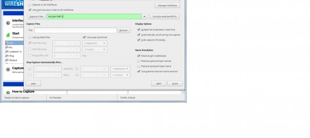
Now with a VNC client you can connect to your RPi and start wireshark in a terminal. You can use not (port 5901) as capture filter which does not capture the VNC traffic.

wireshark capture

How to setup a static IP address raspberry PI

You cannot get a static or fixed IP address working on you Raspberry PI with the current tutorials? Then you came to the right place!

The raspberry PI is an excellent device and I use it often as a server to host my projects. For most of my project I need a static IP address on my RPi. I thought that this would be an easy job just to change the /etc/network/interfaces (also according to a lot of tutorials).  Turns out that from the jessie image (kernel 4.x) you need to change the dhcpd.conf. Below I will explain in detail the steps and some more guidance on where to configure your static IP address.

Network

Before you add a static IP address on your RPi, please consider where you want to make the configuration. It makes a lot of sense to configure your DHCP server (in most home networks your ISP router) with the appropiate settings rather then on the RPi.  Based on the MAC address of your device the router is able to hand out a static IP address. Configuring this on your router makes administration easier due to the fact that you have 1 administration where all the data of the devices with a static IP address is stored.

Bonjour

Now that you have configured your router and your RPi has a static IP you can log on to the given IP address. But we people are better in remembering a name than numbers. So to make life more easier you can install avahi on your RPi.

Avahi is a linux implementation which enables programs/OS to publish and discover services and hosts running on a local network. For example, a user can plug their computer into a network and have Avahi automatically advertise the network services running on the machine which could enable access to files and printers.

The protocol behind avahi is known as Multicast Domain Name Service (mDNS) and can also be used as a system for local DNS resolution. Also apple addopted this protocol and implemented it in bonjour. Probally a lot of your devices in your network are already using this, eg. Chromecast, NAS server, open elec and arduino yun.

Next to boradcasting the services available on your host you can also reach your device by using the hostname and the .local suffix. E.g. ping monitoring.local

> ping monitoring.local
PING domotiga.local (192.168.2.30) 56(84) bytes of data.
64 bytes from 192.168.2.30: icmp_seq=1 ttl=64 time=3.87 ms
64 bytes from 192.168.2.30: icmp_seq=2 ttl=64 time=42.6 ms
64 bytes from 192.168.2.30: icmp_seq=3 ttl=64 time=66.6 ms

You can enable this on your RPi:

sudo apt-get update
sudo apt-get install avahi-daemon

Go ahead and ping the new .local address on the machine you wish to access the device from! If you installed Itunes on your windows machines you also have the bonjour service installed. If not, just donwload it from the apple website. You can now use this on your CLI but also from your webbrowser. If you want to browse through al available services/clients please install the avahi utils:

apt-get install avahi-utils
avahi-browse -a -t

The browse command will provide you with all available service:

+ wlan0 IPv4 DiskStation Apple File Sharing local
+ wlan0 IPv4 DiskStation _device-info._tcp local
+ wlan0 IPv4 Woonkamer _googlecast._tcp local
+ wlan0 IPv4 monitoring Remote Disk Management local
+ wlan0 IPv4 domotiga Remote Disk Management local

Static on Raspberry PI

Still you can have a good reason not to configure the static IP address via your router, in my case it was a network related project.  Probally you already tried some configuration changes to the /etc/network/interface file. Please undo them. If you did not make a backup, you can use below config:

# Include files from /etc/network/interfaces.d:
source-directory /etc/network/interfaces.d</code>

auto lo
iface lo inet loopback

iface eth0 inet manual

allow-hotplug wlan0
iface wlan0 inet manual
wpa-conf /etc/wpa_supplicant/wpa_supplicant.conf

allow-hotplug wlan1
iface wlan1 inet manual

You can now edit /etc/dhcpcd.conf and please add:

interface eth0
static ip_address=x.x.x.x/24
static routers=x.x.x.x
static domain_name_servers=8.8.8.8

In my case I was connected via SSH, so you can now reboot RPi.