Serial UART connection RPI zero / Arduino

You can connect the RPI and Arduino is several ways, eg. Serial/UART, I2C or USB. With I2C you can connect several device on the same wire. 1:1 communication is now suffiecient so I will go for the Serial/UART connection.

The RPI operates at 3.3V and the arduino I have chosen on 5V. Therefor we should use a Logic Level Converter (LLC) for serial/UART communication. If you are going for I2C please use the I2C converter.

Wiring

There are 12 total pins on the LLC – two parallel rows of six headers. One row contains all of the high voltage (e.g. 5V) inputs and outputs, the other row has all things low voltage (e.g. 3.3V).

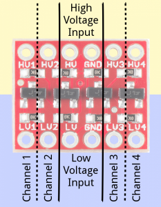
The voltage supplied to the HV and GND inputs should be higher than that supplied to the LV side. For example, if you’re interfacing from 5V to 3.3V, the voltage on the HV pin should be 5V, and the voltage on LV sould be 3.3V.

There are four separate data channels on the BD-LLC, each capable of shifting data to and from high and low voltages. These pins are labeled HV1, LV1, HV2, LV2, HV3, LV3, HV4, and LV4. The number at the end of each label designates the channel of the pin, and the HV or LV prefix determines whether it’s on the high or low side of the channel.

A low-voltage signal sent in to LV1, for example, will be shifted up to the higher voltage and sent out HV1. Something sent in HV3 will be shifted down and sent out of LV3. Use as many of these channels as your project requires.

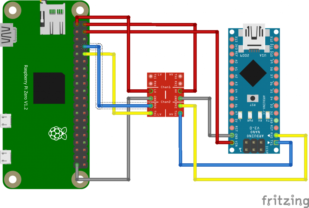
The RPI is the low level side and the Arduino on the high level side. Please note that for the GPIO the RPI uses 3.3V, but still it has pins to provide 5V. I use the RPI 5V pins to provide power to the Arduino Nano board. We can also use the other RPI 5V pin to provide the HV side for the Arduino. We also need to twist the TX/RX, check this cross on the LLC board (blue/yellow crossing).

RPI config
The RPI is not yet configured to use the serial for communication. Please perform the following steps:
You can use “raspi-config” utility to enable the UART:
1. sudo raspi-config
2. Under “Interfacing Options”, choose “Serial”.
3. Say “No” when it asks if you want a login shell over serial.
4. Say “Yes” when asked if you want the hardware enabled.
5. Finish, then accept the offer to reboot.

After this configuration change and the wiring you are ready to check if the serial communication is ready to use. First you can check if ttyS0 is available on the RPI side with the command ls -l /dev/ttyS0, you should see the following output: crw-rw—- 1 root dialout 4, 64 Mar 22 19:16 /dev/ttyS0

The fastest way to check the communication is to load the following program into your arduino:

int x = 0; // variable

void setup() {
Serial.begin(9600); // open the serial port at 9600 bps:
}

void loop() {
// print labels
Serial.print("NO FORMAT"); // prints a label
Serial.print("\t"); // prints a tab

Serial.print("DEC");
Serial.print("\t");

Serial.print("HEX");
Serial.print("\t");

Serial.print("OCT");
Serial.print("\t");

Serial.print("BIN");
Serial.print("\t");

for(x=0; x< 64; x++){ // only part of the ASCII chart, change to suit

// print it out in many formats:
Serial.print(x); // print as an ASCII-encoded decimal - same as "DEC"
Serial.print("\t"); // prints a tab

Serial.print(x, DEC); // print as an ASCII-encoded decimal
Serial.print("\t"); // prints a tab

Serial.print(x, HEX); // print as an ASCII-encoded hexadecimal
Serial.print("\t"); // prints a tab

Serial.print(x, OCT); // print as an ASCII-encoded octal
Serial.print("\t"); // prints a tab

Serial.println(x, BIN); // print as an ASCII-encoded binary
// then adds the carriage return with "println"
delay(200); // delay 200 milliseconds
}
Serial.println(""); // prints another carriage return
}

This arduino program will print out a list of dec, hex and binair numbers on the serial interface of the arduino.

Now enable the RPI side with:
sudo apt-get install minicom
sudo minicom -b 9600 -o -D /dev/ttyS0

To exit minicom: Hit enter, then ctrl-a then q then press “enter”

Arduino yun MQTT Tutorial

In this tutorial we will dive into the use of MQTT with the arduino yun (or linkit) to control the LED#13.

One of the common protocols used in the IOT world is MQTT. MQTT is a machine-to-machine (M2M)/”Internet of Things” connectivity protocol. It was designed as an extremely lightweight publish/subscribe messaging transport. It is useful for connections with remote locations where a small code footprint is required and/or network bandwidth is available.

MQTT
The MQTT protocol is based on the principle of publishing messages and subscribing to topics, or “pub/sub”. Multiple clients connect to a broker and subscribe to topics that they are interested in. Clients also connect to the broker and publish messages to topics. Many clients may subscribe to the same topics and do with the information as they please. The broker and MQTT act as a simple, common interface for everything to connect to.

The setup
1.) MQTT broker running on a RPI
2.) Python script on the arduino yun (openwrt)
3.) Sketch for the MCU

MQTT broker
To install the MQTT broker:

apt-get update
apt-get install mosquitto

To test it open two SSH connections. One for subscribing and the other for publishing.

mosquitto_sub -h 192.168.2.40 -t "arduino/led"
mosquitto_pub -h 192.168.2.40 -t "arduino/led" -m "1"
mosquitto_pub -h 192.168.2.40 -t "arduino/led" -m "0"

Result:

1
0

For debugging purposes you can also run mosquitto in a shell. So open up the third SSH connection. Execute “/etc/init.d/mosquitto stop” and then execute “mosquitto”. Output:

1468435883: mosquitto version 1.3.4 (build date 2014-08-22 06:10:51+0000) starting
1468435883: Using default config.
1468435883: Opening ipv4 listen socket on port 1883.
1468435883: Opening ipv6 listen socket on port 1883.
1468435883: New connection from 192.168.x.x on port 1883.

Python
Install the MQTT python client:
pip install paho-mqtt

And then use the following python code:


#!/usr/bin/python
import sys
import paho.mqtt.client as mqtt

sys.path.insert(0, '/usr/lib/python2.7/bridge/')

from bridgeclient import BridgeClient as bridgeclient

from tcp import TCPJSONClient
json = TCPJSONClient('127.0.0.1', 5700)

value = bridgeclient()


# The callback for when the client receives a CONNACK response from the server.
def on_connect(client, userdata, rc):
    print("Connected with result code "+str(rc))
        # Subscribing in on_connect() means that if we lose the connection and
        # reconnect then subscriptions will be renewed.
    client.subscribe("arduino/led")

# The callback for when a PUBLISH message is received from the server.
def on_message(client, userdata, msg):
        print(msg.topic+" "+str(msg.payload))
        json.send({'command':'put', 'key':'led', 'value':msg.payload})

client = mqtt.Client()
client.on_connect = on_connect
client.on_message = on_message

client.connect("192.168.x.x", 1883, 60)

# Blocking call that processes network traffic, dispatches callbacks and
# handles reconnecting.
# Other loop*() functions are available that give a threaded interface and a
# manual interface.
client.loop_forever()

Normally I would use value.put() instead of using json.send() only I received a “Bad file descriptor” once in a while. As the arduino yun uses JSON via TCP to the bridge library I used this workaround instead.

Sketch
Upload the sketch. memset will set al the items in the array to zero.

#include <Bridge.h>
#include <stdio.h>
 
// Here we will hold the values coming from Python via Bridge.
char ledvalue[2];
 
void setup() {
  // Zero out the memory we're using for the Bridge.
  memset(ledvalue, 0, 2);
   
  // Initialize digital pins 13 as output.
  pinMode(13, OUTPUT); 
 
  // Start using the Bridge.
  Bridge.begin();
}
 
void loop() {
  
  
  // Write current value of D13 to the pin (basically turning it on or off).
  Bridge.get("led", ledvalue, 2);
  int ledD13 = atoi(ledvalue);
  digitalWrite(13, ledD13);
   
  delay(10);  
}

Please note that the delay for retreiving info from the bridge is rather low, causing heavy load on the linux side.

Update [29-12-2017]:
If you receive the following error: TypeError: on_connect() takes exactly 3 arguments (4 given) the following could help you. Paho-mqtt client has been updated and you need to change the following (1. on_connect and subscribe):

def on_connect(client, userdata, rc):
print(“Connected with result code “+str(rc))
# Subscribing in on_connect() means that if we lose the connection and
# reconnect then subscriptions will be renewed.
client.subscribe(“arduino/led”)

Should be changed to:
def on_connect(self, client, userdata, rc):
print(“Connected with result code “+str(rc))
# Subscribing in on_connect() means that if we lose the connection and
# reconnect then subscriptions will be renewed.
self.subscribe(“arduino/led”)

Arduino yun bridge Tutorial

The Yún has two processors on board. One is an ATmega32U4 like on the Arduino Leonardo (we call it MCU from now on). The other is an Atheros 9331 (we call it MPU from now on), running Linux and the OpenWRT wireless stack, which enables the board to connect to WiFi and Ethernet networks. This tutorial also works for the linkit 7688 Duo. To run it on a linkit, please enable the arduino yun bridge software. You can find it in my older posts.

The bridge has quite some options available, for me there are two use case who are practical for me:
1.) Sending sensor data from the MCU to a server
2.) Bi-directional communication between a server and the MCU

Sending sensor data from the MCU to a server
Say for example that you have a sensor which can measure the temperature and partical concentration and you want to upload it to a restfull api webserver. In this case you are only sending data from the MCU to a server. Easiest solution is to use the “runShellCommand”. As the functionname tells us, it runs a command in the shell.

There are two flavours, runShellCommandAsynchronously() and runShellCommand(). runShellCommand() is a blocking function. That is, once you call Process.runShellCommand(), nothing else will happen in your sketch until it has completed. The time depends on the nature of the command you are executing. For a non-blocking alternative, please use runShellCommandAsynchronously().

Now we have a solution to run from your sketch a shell command. Now we have access to the shell, we need a tool to upload our data to the server. We can use Curl for this. Curl is an open source command line tool and library for transferring data with URL syntax. Eg. you can download a webpage, or upload via json data to a restfull api.

#include <Process.h>

void setup(void) {
  Bridge.begin();
}

void loop(void) {
  String curlCmd;

  String resultConcentration;
  String resultTemperature;
 
  resultConcentration=5.5;
  resultTemperature=20.0;
  
  curlCmd = "curl -H \"Content-Type: application/json\" -X POST -d \'{\"concentration\": "+resultConcentration+", \"temperature\": "+resultTemperature+"}\' http://192.168.x.xx:8080/measurement";

  Process database;
  database.runShellCommand(curlCmd);
  delay(1000);
}

You need to include for the bridge communication. “Bridge.begin()” starts Bridge, facilitating communication between the MCU and MPU. This should be called once in setup(). begin() is a blocking function. Once you call Bridge.begin(), nothing else will happen in your sketch until it has completed. This process takes approximately three seconds.
Process is the base class for all Bridge based calls for communicating with the Yun’s shell. Followed by run() or runAsynchronously(). The named process does not start executing until run() is called.

Bi-directional communication between a server and the MCU
For bi-directional communication you need to have a program/script running on the MPU. This will have a connection to a server (Eg. MQTT broler) and read/writes to the bridge. On the MCU you will need to have a sketch which can read/write to the bridge.

Sketch
The put() function allows you to store data on the MPU using a Key/Value structure. The Key field is like a label and you can associate a value to it. The key name must be unique in order to identify the correct value. On the MPU side there is a data store where all the keys and the values are saved.

The datastore is saved in the RAM of the MPU (AR9331), you will lose the datastore when you restart the bridge software on the Linux side (through power cycling, resetting the Linux processor, or uploading a sketch through WiFi or Ethernet). You will not lose the datastore if you reset the MCU (ATMega32u4 processor).

get() allows you to read a key/value item previously saved on the MPU. You can request for a value stored in the datastore by passing get() the Key you want to search for, the support buffer, and its size. The Key is similar to a label, used to identify an associated value. The key name must be unique in order to identify the correct value.

#include <Bridge.h>

unsigned long timer;
unsigned long counter = 0L;

void setup()
{
    Bridge.begin();     // this launches /usr/bin/run-bride on Linino
    timer = millis();
    Serial.begin(9600);
}

void loop()
{
    /* Every 200ms: */
    char bridge_Value[6];
    
    if (millis() - timer > 200) {
        timer = millis();

        Bridge.put("counter", String(counter++));
        Bridge.put("random1", String(random(1, 100)));
        Serial.println(counter);
        Bridge.get("hello", bridge_Value, 6);
        Serial.println(bridge_Value);
    }
}

Python script
For the MPU I’ve chosen to use a python script. You need to import the bridge library. The code is rather self explaining. You can also access the data via the API of the arduino Yun. In our case you can use http://192.168.x.xx/data/get/counter to read the value of counter, or write to counter via http://192.168.x.xx/data/put/counter/4

#!/usr/bin/python
import time
import sys

sys.path.insert(0, '/usr/lib/python2.7/bridge/')

from bridgeclient import BridgeClient as bridgeclient

value = bridgeclient()


while True:
        message = value.get("counter")
        print message
        value.put('hello','world')
        time.sleep(1)
        value.put('hello','you')

The sketch code is based on code from Jan-Piet Mens. The python from alnitak1000. I combined both the bridge.put()/bridge.get() and value.put()/value.get() together.

Enable Arduino Yun bridge on Linkit 7688 Duo

If you already have code written for your Arduino yun which uses the Yun bridge and you want to run it on your Linkit 7688 Duo you can also enable this library.

Use following commands to enable Bridge library on LinkIt Smart 7688 Duo:

uci set yunbridge.config.disabled='0'
uci commit
reboot

In your sketch you can now add Bridge.begin(); in the setup which will trigger the run-bridge shell script which invokes python bridge.py from /usr/lib/python2.7/bridge.

Linkit 7688 Duo DHT22

Both the Linkit 7688 and DHT22 are low cost components and can perfectly be used as a IOT temperature and humidity device. Using the openwrt part of the linkit to upload all the data to your server.

DHT22 specs:

  • 3 to 5V power and I/O
  • 2.5mA max current use during conversion (while requesting data)
  • Good for 0-100% humidity readings with 2-5% accuracy
  • Good for -40 to 125°C temperature readings ±0.5°C accuracy
  • Body size 15.1mm x 25mm x 7.7mm

The DHT22 has has four pins

  • VCC (3 to 5V power)
  • Data out
  • Not connected
  • Ground

You can ignore pin 3, its not used. Please use a pull-up resistor between VCC and the data pin (10k).

Below pictures shows the connection diagram.

Linkit 7688 Duo DHT22

Now we need to install the DHT library. You can find the latest libraries here: https://github.com/adafruit/DHT-sensor-library

Or download from my website: DHT-sensor-library-master

You can use the following sourcecode written by layada. If you download the libraries you can also get the code from the example menu.

// Example testing sketch for various DHT humidity/temperature sensors
// Written by ladyada, public domain

#include "DHT.h"

#define DHTPIN 2 // what digital pin we're connected to

// Uncomment whatever type you're using!
//#define DHTTYPE DHT11 // DHT 11
#define DHTTYPE DHT22 // DHT 22 (AM2302), AM2321
//#define DHTTYPE DHT21 // DHT 21 (AM2301)

// Connect pin 1 (on the left) of the sensor to +5V
// NOTE: If using a board with 3.3V logic like an Arduino Due connect pin 1
// to 3.3V instead of 5V!
// Connect pin 2 of the sensor to whatever your DHTPIN is
// Connect pin 4 (on the right) of the sensor to GROUND
// Connect a 10K resistor from pin 2 (data) to pin 1 (power) of the sensor

// Initialize DHT sensor.
// Note that older versions of this library took an optional third parameter to
// tweak the timings for faster processors. This parameter is no longer needed
// as the current DHT reading algorithm adjusts itself to work on faster procs.
DHT dht(DHTPIN, DHTTYPE);

void setup() {
Serial.begin(9600);
Serial.println("DHTxx test!");

dht.begin();
}

void loop() {
// Wait a few seconds between measurements.
delay(2000);

// Reading temperature or humidity takes about 250 milliseconds!
// Sensor readings may also be up to 2 seconds 'old' (its a very slow sensor)
float h = dht.readHumidity();
// Read temperature as Celsius (the default)
float t = dht.readTemperature();
// Read temperature as Fahrenheit (isFahrenheit = true)
float f = dht.readTemperature(true);

// Check if any reads failed and exit early (to try again).
if (isnan(h) || isnan(t) || isnan(f)) {
Serial.println("Failed to read from DHT sensor!");
return;
}

// Compute heat index in Fahrenheit (the default)
float hif = dht.computeHeatIndex(f, h);
// Compute heat index in Celsius (isFahreheit = false)
float hic = dht.computeHeatIndex(t, h, false);

Serial.print("Humidity: ");
Serial.print(h);
Serial.print(" %\t");
Serial.print("Temperature: ");
Serial.print(t);
Serial.print(" *C ");
Serial.print(f);
Serial.print(" *F\t");
Serial.print("Heat index: ");
Serial.print(hic);
Serial.print(" *C ");
Serial.print(hif);
Serial.println(" *F");
}

With the arduino ide 1.6.9 you will receive a compile error “magic key not defined”. You can download and use the hourly builds to solve this issue.

The serial output will look like this:

Humidity: 49.40 % Temperature: 25.00 *C 77.00 *F Heat index: 24.85 *C 76.72 *F
Humidity: 49.40 % Temperature: 24.90 *C 76.82 *F Heat index: 24.74 *C 76.52 *F
Humidity: 49.40 % Temperature: 25.00 *C 77.00 *F Heat index: 24.85 *C 76.72 *F

The fritzing parts you can download here:
LinkIt_Smart_7688_Duo_DHT22_diagrams

Linkit 7688 No Wifi after initial boot

After unpacking the Linkit Smart 7688 and power it up I did not get any Wifi network.

Normal behaviour: After the boot loader has initialized the boot up process begins, which takes about 30 seconds. Next, the Wi-Fi LED turns off; this means the system is ready to accept a Wi-Fi connection. The 7688 becomes an access point (AP) based on his mac address (LinkIt_Smart_7688_XXXXXX, where xxxx is the mac address)

Unfortunately I did not see any SSID broadcasted. To solve this please do a factory reset using the Wifi button (middle button).

Procedure:

  1. Boot up the board and wait for the Wi-Fi LED to go off.
  2. Press and hold the Wi-Fi button for at least 20 seconds and release.
  3. The Wi-Fi LED will blink fast for 1 second while performing a factory reset.

Now you can connect to the board.

RC522 with Raspberry Pi 2

The RC522 is a cheap RFID module that can read and write Mifare’s tags and being sold at several web stores, like eBay and included with many “starter kits” nowadays. Simply search RFID-RC522 (MF-RC522). The card reader and the tags communicate using a 13.56MHz electromagnetic field. (ISO 14443A standart tags)

Wiring up:

Below table shows the connection between RC522 and RPi2:

RC522 pin RPi2 pin nr RPi2 pin name
SDA 24 GPIO8
SCK 23 GPIO11
MOSI 19 GPIO10
MISO 21 GPIO9
IRQ Remark: Not connected
GND GND GND
RST 22 GPIO25
3.3V 1 3V3

Please note that the RPi2 has a 40 pin header (RPi1 has 25).

Wiring RPi2 and RC522

RPi2 steps:

We need to enable all the python libraries and the SPI interface on the RPi2 to get it working.

To install the python environment:

sudo apt-get install python-dev

enable spi interface:
Edit the file /boot/config.txt and add the following two lines:

device_tree_param=spi=on
dtoverlay=spi-bcm2708

To check if the SPI interface is working, please reboot the RPi and run the following instructions:

$ dmesg | grep spi

The output will look like:

[ 10.886588] bcm2708_spi 3f204000.spi: master is unqueued, this is deprecated
[ 10.901487] bcm2708_spi 3f204000.spi: SPI Controller at 0x3f204000 (irq 80)

Now download and install the SPI python library:

git clone https://github.com/lthiery/SPI-Py.git
$ cd SPI-Py
$ sudo python setup.py install

Now download and run the RC522 lib:

$ git clone https://github.com/rasplay/MFRC522-python.git
$ cd MFRC522-python
$ python read.py

The output will look like:

Card detected
Card read UID: 98,40,242,197,125